Improve "Sketch in New Workplane" by adding two way of construction#1054
Improve "Sketch in New Workplane" by adding two way of construction#1054phkahler merged 2 commits intosolvespace:masterfrom
Conversation
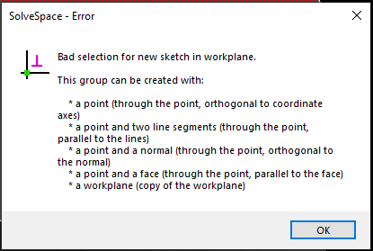
- point and normal
- point and face
|
|
|
@MaxiPaille This is a nice change. Not sure if you realize what's going on here vs what the original request was in #1048. They wanted to select a line and a point to create a workplane. What you've implemented is to select a normal and a point. A normal in Solvespace is represented by a quaternion, which is a full orientation and not just a direction vector. A workplane has to have a U and V axis, whcih can be pulled from the quaternion, or derived from 2 line segments and some cross products to ensure they're orthognal. What you've implemented here is definitely a nice improvement, but I wanted to point out how its different from the original issue/request. Another thing might be to allow using just a face without having to also select a point. I think each face is defined by a point and a quaternion. What you've implemented should also allow creating a workplane parallel to a face but at some distance depending which point was selected. It seems like another line or two of code should allow it to work by selecting only the face. These are my comments after looking at the commit without even trying it yet ;-) It looks good! |
|
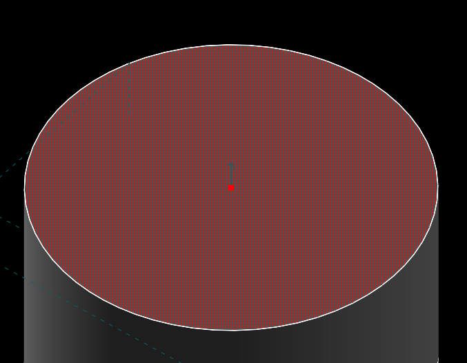
@MaxiPaille There is something wrong. If I use extrude to create a cylinder they way you've shown it works. When I draw a rectangle and use lathe to create a ring, select a point and the top face and press shift->W I get a workplane through the cross-section of the ring rather than on the top face. I'm not sure why this happens. This may need a little more understanding on how a face is represented. @jwesthues can you offer any insight here? |
|
The lathe faces are created in Group::MakeLatheSurfacesSelectable() I tried changing from: to: Which seem to be a very different function (it's in util.cpp) but there was no change. The workplane is still wrong when selecting a face created by lathe. |
|
Hey @phkahler, I'm happy to hear that this is a nice improvement :). I understand that my pull request do not answer what is discussed in the feature request #1048 originally. I was mainly focus on the fact that the simpliest way to describe a plane is a combination of a point and a normal and the software did not support it out of the box. Sorry for the confusion. I wanted to implement the "face only" way you suggested but i'm not sure how to get the hEntity of the origin point from a face Entity. The only method I found is FaceGetPointNum() that return the Numerical value but the predef structure takes a hEntity as origin. If you can help me on this, it would be very cool. I'm also think about implementing a "3 points" way. I imagine we could take the orientation of the camera to infer the normal direction, as we do with the "1 point" method. What do you think? |
|
Regarding the lathe bug, I've just break into the "point + face" method. The normal of the face seems ok. I bet there is an issue with the Quaternion::From(direction, 0). |
|
I think the confusion is that SolveSpace normals in general are "oriented", representing 3 DOF equivalent to a unit quaternion (or 3x3 rotation matrix), as @phkahler notes above. We need this when we create the workplane, since that determines the rotation of the u and v vectors about n (which determines e.g. the rotation within the plane of our monitor when we View -> Align View to Workplane, or what the horizontal and vertical constraints do). But for "workplane from face", the normal to a face is un-oriented, representing 2 DOF equivalent to a unit 3-vector. So we need some algorithm to choose that last degree of freedom, the twist about n. We could allow the user to select a line and use the projection of that line into the plane for u, or if all we have is the face we could just use For "workplane from [oriented] normal", there's no fundamental problem; the code just seems wrong. We just need to copy all four elements of the original normal's unit quaternion, and not reduce it to a 3-vector like now. Probably also good to name new workplane subtypes, since these aren't Final observation, note that even though the "oriented normal" has 3 DOF, we represent it as four scalars in a unit quaternion, and even though the "unoriented normal" has 2 DOF, we represent it as three scalars in a unit 3-vector. Neither geometric concept can be represented in any well-behaved mathematical form without that extra scalar and extra (unit length) constraint, due again to something like the hairy ball theorem. |
|
Hello @jwesthues, Thanks for you detailed answer. What I understand is that you have an extra scalar for each type of data to be able to keep orientation when needed (creation of workplanes for example). Knowing that, my "improvements" are indeed totally wrong. Now I understand why it's not simple to implement. Regarding the Subtype, I wanted to be as less invasive as possible. But if you think it's worth it, I will create a subtype for each new way I'll add. Thanks for your time. |
|
@MaxiPaille No problem at all, and the feature makes sense to me too. SolveSpace's use of the word "normal" to mean "oriented normal" is nonstandard, and thus a bit of a trap for new contributors. The solution for "workplane with normal" is as you say, straightforward. The solution for the others requires a bit of math; but if you plan to do more work in SolveSpace (or any other software development involving solid geometry), then I believe you'll find the effort to learn that worthwhile. Let us know if you have questions... |
@jwesthues For Lathe and Revolve groups we could define the U vector as being in the direction of the line that sweeps out the face. V would be the rotation axis.Cross(U). Would it break compatibility if we redefined it as an "oriented normal"? We might want to revisit all of the face creation if possible - the idea of selecting a face and pressing Shift->W to draw on it is really nice, but probably not at the cost of incompatibility. |
|
@phkahler Yeah, I was thinking that too. The source geometry always provides a u vector, so it was a bad decision to discard that information. I think you could add that back without breaking backwards compatibility, since you're strictly adding information, though you'd have to support both the old and new representations to avoid breaking old linked files. |
…on of workplane

Temporary disable other ways because of wrong implementation
|
If I understand correctly, you aim to refacto the face creation to always keep an "oriented normal" in the face entity? And there is too much type of face I don't understand yet... But if I could help, let me know. I will continue to dig the source code on my side. |
|
@MaxiPaille That was the idea above. I still need to understand more and I think there will be a compatibility issue for sure. Face entites are created in the following functions: There may be some other places like when a group is copied. Trouble is, if we change the definition for a face normal to include the U,V coordinate system definition that is probably going to break some things like point-on-face constraints. I'm not sure if those equations are regenerated which might define them in new terms if so. Some stuff I've written about the entity types can be found in the solve transforms document More documentation on the internals really needs to be written ;-) Redefining face normals would require updating some of the functions in entity.cpp to return numeric values and expression differently. It's a fairly big job, and a really big one to ensure comaptibility. If you want to attempt it I'd suggest changing one of the functions above to produce a normal that's compatible with your pull request here, along with the normal functions in entity.cpp. If you can then define a work-plane using the modified surface then you're on the right track. Changing the other 3 functions should go a long way. Then you (or someone) needs to look at the constraint creation involving faces. I'm not sure there is anything else to change for new sketches - there almost always is - but the ability to use old sketches will be a requirement to merge it into master and I have no idea how to do that. Well some ideas but none that I think are good yet. Solvespace does need more developers, so if you're interested keep hacking away at it. There are people familiar with most if not all of the code so just ask. |
|
Also, see issue #423 |
|
Thanks for your detailed answer. Glad to see that other people want this feature too. I will read your documentation and try to understand everything. Does the project have a discord or somewhere to discuss ? Not sure if i should flood this thread in case of basic questions about code and stuff. |
|
@MaxiPaille I'm currently working on a PR #1057 for mirror groups which involves making a new copy-type in entity.cpp. It's partly working, but faces are normals are maybe not right yet ;-) BTW I am using the existing convention for normals which I understand better now after all the discussion. |
|
Merging this. While using a normal this way may not be the most common thing to do, there's no reason it shouldn't work if someone tries it. Also a very small code change. |
|
Which version this feature is available in? I have 3.0, but there is none... |
|
Edit: The point and face was disabled as part of this commit: |
…normal

It is now possible to create a "New Group | Sketch in New Workplane" from
an existing workplane defined using a point and a nowmal. Before we used to
hit the `ssassert(false, "Unexpected workplane subtype");`.

This makes 4308dc1 more complete and
is related to solvespace#1120, solvespace#1048 and
solvespace#1054
…normal

It is now possible to create a "New Group | Sketch in New Workplane" from
an existing workplane defined using a point and a nowmal. Before we used to
hit the `ssassert(false, "Unexpected workplane subtype");`.

This makes f27de77 more complete and
is related to solvespace#1120, solvespace#1048 and
solvespace#1054
I improved "Sketch in New Workplane" by adding two way of construction:
point and normal
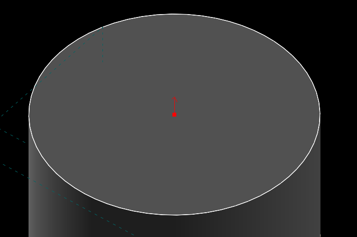
point and face
I also added description in error popup:
I tried to be as less invasive as possible, and also tried to respect the coding style.
I have tested this code on Windows only.